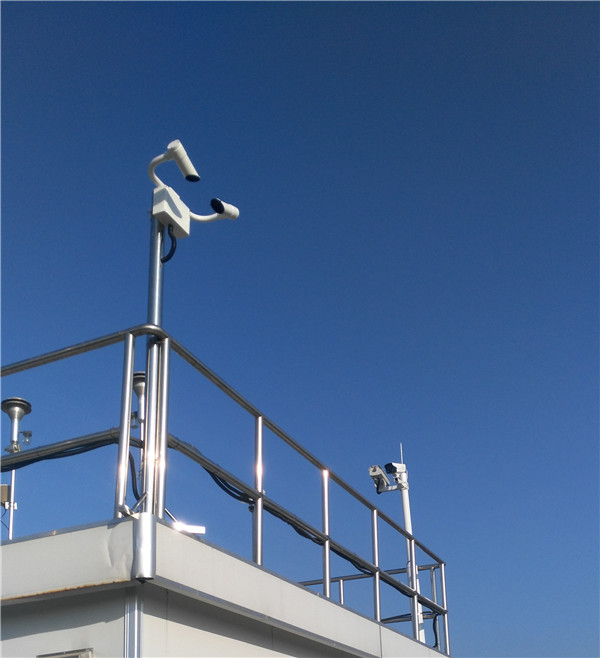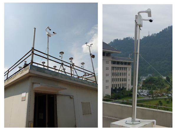
In response to the new national regulatory requirements and market demand, some prefecture-level air monitoring substations need to add the construction of urban environment photography systems, which can be divided into visibility photography systems and indoor (outdoor) security systems.
In the General Station Air Letter [2013] No. 33, for visibility photography systems, it is generally required to be able to achieve continuous photography under user-specified conditions, and to be able to synchronously achieve remote transmission of the captured images, or to be able to trigger photography in conjunction with visibility monitoring instruments to form photos with superimposed data, and to remotely transmit the captured images.
For indoor (outdoor) security systems, it is generally required to take real-time photos of the key indoor and outdoor parts of the monitoring substation station, and store them in the computer system of the hosting station, with a storage period of at least 2 weeks.
The following is a detailed description of the visibility photography system that needs to be linked with the visibility monitor.
1. System Introduction
At present, environmental protection bureaus in various places are strengthening the automatic monitoring business of haze in air quality monitoring substations. In addition to the conventional monitoring indicators of SO2, NOx, PM10, CO, O3, and PM2.5, the Ministry of Environmental Protection's 12th Five-Year Plan also clearly states that it will establish a complete quality control management mechanism for substations in key cities and subsequent prefecture-level cities and even county-level rural background stations, and it is also necessary to increase the supporting atmospheric visibility visual monitoring system (also known as visibility photography system).
2. System composition
The visibility visual monitoring system is divided into outdoor front-end equipment and indoor background monitoring computer. The front-end equipment installed outdoors at the substation mainly includes visibility meter and high-definition camera. The ASHUR-VD920 visibility meter itself is a standard RS232 data interface, which can be converted into Ethernet transmission through the RS232-RJ45 module. The visibility instrument, 100M network port high-definition camera and indoor monitoring computer are connected through routing or switching equipment. The indoor monitoring computer can accurately locate the front-end device through the IP address. The communication protocol of the entire system can use TCP or UDP. The background computer uploads or opens related interfaces via FTP, which can provide the substation monitoring data to be shared with the remote background.

Visibility photography system architecture diagram
3.1 Data acquisition and transmission
The visibility meter can be converted into Ethernet transmission through the RS232-RJ45 module. The selected 100M network port HD camera can be directly connected to the switch. The background monitoring computer in the same network segment of the switch can accurately exchange data with each front-end device through the IP address. The entire system communication protocol can use TCP and UDP.
The visibility meter actively uploads measurement data and its own status information once a minute.
The 100M network port HD camera can take pictures at preset time intervals, or the background computer can be set to detect that the visibility value reaches the preset alarm threshold to trigger the camera to capture in real time.
The background computer can upload or open relevant interfaces through FTP, which can provide the monitoring data of the substation to the remote and more secure background.
3.2 Data monitoring and processing
Whether it is a scheduled or early warning mobile capture, the background computer will superimpose the current time, site location, visibility measurement value and other character information with the photo in real time. The processed composite photos will be stored locally according to the site and time level, and can be queried at any time.
The background computer will monitor the working status of the visibility meter and high-definition camera, as well as the visibility measurement data in real time. When one item reaches the preset alarm threshold, it will immediately alarm the user in the form of color, sound or even pop-up window.
3.3 Data query and output
The system is equipped with a large database, and the composite images superimposed with character information will be compressed and stored according to the internationally accepted MPEG-2, JPEG or H.264 compression algorithms.

Application Image